Bode diagram and power and efficiency with a parallel circuit Parallel rlc plots bode circuit case shows pages preview Resonant frequency from bode plot
Solved For the RLC circuit shown in Figure 1, derive the | Chegg.com
Solved the bode plot of the rlc circuit shown in fig. 1. Signal processing Bode circuit rl diagram transfer function create
Rlc derive chegg eo laplace
Bode parallel circuitSolved question 3: this “rlc” circuit with input voltage Bode rlc parallelBode rlc plot bandwidth transcribed.
Engr 301 lab 1Bode plot rlc filter bandpass parallel q5 solved below represents transcribed problem text been show has Solved q5: the bode plot below represents a parallel rlcBode rlc values fig different circuit response plots lab1.

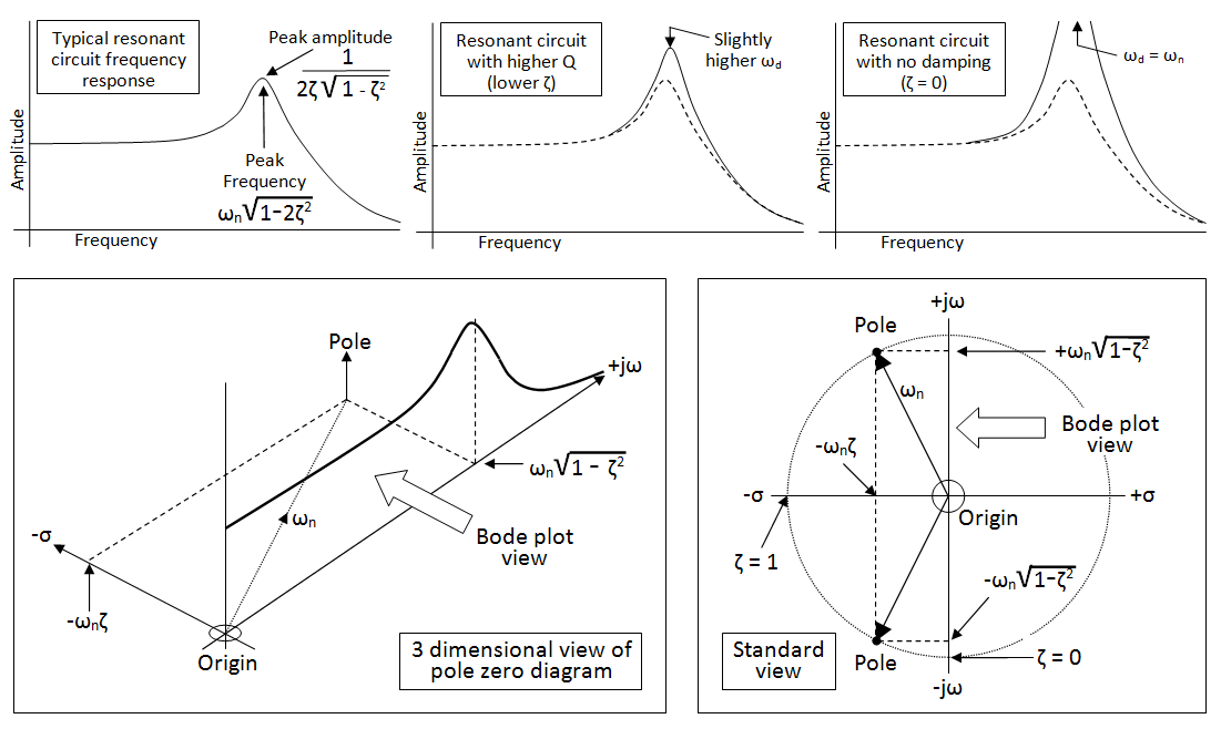
Bode frequency plot pole poles filter pass diagram low response factor plane resonant zeros domain 3d system order high find
Bode diagramsBode diagram for rl circuit Bode plots parallel rlcBode diagrams electronics circuit.
Solved for the rlc circuit shown in figure 1, derive theThis "rlc" circuit with input voltage "vi(t)" and .


Solved QUESTION 3: This “RLC” circuit with input voltage | Chegg.com
Resonant Frequency from Bode plot - Electrical Engineering Stack Exchange

Solved Q5: The bode plot below represents a parallel RLC | Chegg.com

Bode Diagrams - Electronics-Lab.com

signal processing - Bode plot parallel RLC circuit - Mathematics Stack

Solved The Bode plot of the RLC circuit shown in Fig. 1. | Chegg.com

Bode diagram for RL circuit - Electrical Engineering Stack Exchange

Bode diagram and power and efficiency with a parallel circuit

This "RLC" circuit with input voltage "vi(t)" and | Chegg.com

Bode plots parallel RLC - Parallel RLC circuit Case 1: R 10 L 1 Z Y arg